Cam Dynamics |
In this article we’ll look
at the impact of the rotation of the cam on the dynamics of the valve train. For
most road riders understanding the cam dynamics is of purely academic interest
as a Velo OHV valve train is well designed and it is unlikely they will
experience any problems. However, for those owners who race or want to use the
full performance of their engine on the road it can be critical as a common
source of failure is either significant cam wear, valve breakages (due to high
impact loads) or the valve making contact with each other and / or the piston.
A cam rotates at half engine speed and in doing so the cam generates a
rotational velocity relative to the followers. More importantly the as the cam
follower begins to be lifted by the cam, it produces lift which produces a lift
velocity.
If we could design a perfect cam (which we can’t), it would
have a constant velocity profile, which would produce no acceleration. It’s this
acceleration, which produces the force that either causes the valve train to
lose contact with the cam (valve float) or create destructive forces on the
valve train (cam, followers, pushrods, top rockers, valve springs and valve).
Modern engine designers go even further to look at the rate of change of
acceleration, which is called Jerk and the rate of change of Jerk….however for
our interests, we’ll only look at lift, velocity and acceleration. Similarly,
cam designers over the years have used different equations to generate lift
curves such has harmonic, sinusoidal, polynomial to achieve their desired cam
dynamics. Again, this is beyond the interest of most of us.
To analyse
valve dynamics engine designers use powerful computer programmes, which
calculate the lift, velocity and acceleration every degree of rotation or less.
For this analysis I’m grateful to Ingbrigt Valberg who not only provided a
spreadsheet, which I’ve modified to perform the calculations every five degrees
of crankshaft rotation, but also reviewed this article. Even when calculations
are made at every degree of rotation, the minor variations in measurements
produces ‘noise’, which professional programmes ‘smooth’ by applying what are
essentially a series of averaging calculations.
So let’s start looking
at the dynamics, which purely for consistency and ease of comparison I have only
shown for the inlet lobe of the cam.
Looking at the acceleration graphs
that follow you will notice that acceleration and therefore the resulting force
has both a positive and negative component. The positive component during the
first part of the lift curve exerts a force via the cam follower on the cam. At
the point it passes through the zero axes, this force changes to a negative
force i.e. the valve gear without spring pressure would attempt to loose contact
with the cam. Where the forces are positive the valve gear is said to be under
the control of the cam, when the forces are negative, the valve gear is under
the control of the valve spring.
You will recall from the last article
that the M17/2 had an almost identical lift profile to the M17/3, with the
exception of the later cam having quietening ramps. The following lift, velocity
and acceleration diagrams shows the effect of the ramp.
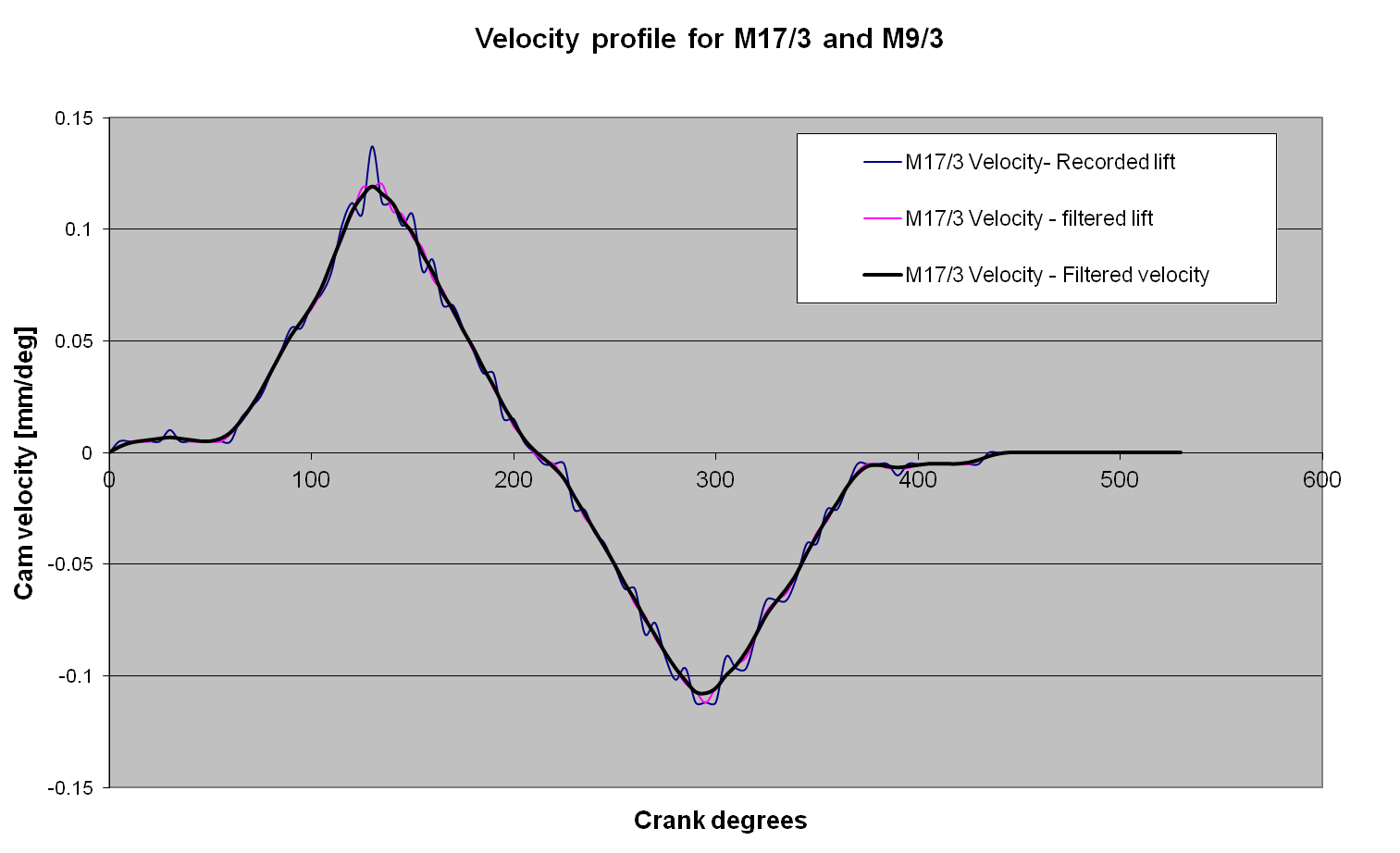
The velocity diagram clearly shows the effect of the
ramp in the early part of the lift curve, but the overall velocity curve and
maximum velocity is similar.
Next we'lll look at the effect increasing
the dwell of the cam, but keeping the lift up and lift down profile similar. For
this we will compare a M17/8 cam together with a modified M17/8 which has been
reprofiled to increase the duration.
As
you would expect the velocity and acceleration curves are similar, however we
can clearly see that the cam has been modified by increasing the dwell of the
cam slightly at the highest lift point, which produces a drop in acceleration at
at about the 260 degree mark.
What the graphs
above clearly show is that compaired to a M17/8, the additional lift and
extended dwell of the Polydyne cames comes at the price of much higher
acceleration. This is particularly noticable on the negative portion of the
accelleration curve where the valve gear is controled by valve springs. What can
also be seen from the lift, velocity and acceleration curves is the impact of
the large dwell period at about 260 degrees wchic reduces the acceleration to
zero. Obviously if you are using this cam for racing it would benefit from
lightened valve gear and a set of valve springs whose force chareteristics
better match the acceleration profile of the cam.
Finaly, lets look at
the profiles of the first M series cam Veloce designed, the M17. Hopefully by
now you can interperate the curves yourself. What’s interesting is that the
maximum negative acceleration where the valve gear is under the influence of the
spring is a similar value to the M17/2, 3 8.